
Compared to other cartridge valves, slip-in cartridge valves are significantly different in the sense that they are a pilot-to-close and two-way directional type of check valves. Most system circuits are utilizing slip-in cartridge valves stream at least 65 GPM and can extend to more than 2500 GPM.
Not only that, but slip-in cartridge valves are also compact, meaning they have a low drop of pressure and can operate up to 5000 psi flow pressure. One thing that makes these valves more efficient for operation is that they can function as flow, pressure, and directional cartridge valves.
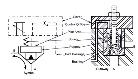
For more details about how these valves work, let’s find out below.
Slip-in Cartridge Valves: Why Use Them?
The major reason why industries are making use of slip-in cartridges in great circuits flow is that they’re economical. Valves with large spool are available with a high capacity flow; however, only a few are being manufactured. Thus, making these valves expensive with delivery times that take too long. An ideal choice is a slip-in cartridge valve piloted by a size D05 control directional valve in a manifold exterior.
Also, a slip-in cartridge valve has one significant feature and that is it has no A port bypass. In terms of leakage, it is somehow the same as any cartridge valve. As for B port, it is greatly low since the leak path is lengthy and has a close tight fit. Hence, when using this type of cartridge valve, remember to utilize the A port, especially for an application that must completely block the flow.
Slip-in Cartridge Valves: How They Work
The most typical slip-in cartridge valve has a 1:2 area ratio since this is a directional control valve. A pilot-to-close cartridge valve has equal port sizes for both port A and B. Also, there are no holes for flow transition through the poppet area. All fluid flow passing through port A or port B moves the poppet widely open in order for the fluid to flow either way. However, such movement will only be restricted by the spring that connects the poppet.
It is also convenient for flow to pass through either valve direction that can be obstructed by pressure on the pilot section. The pressure must be greater than or the same pressure at both ports A and B. when there is the same pressure in both of these ports, the pilot section pressure should also be the same or greater.
These slip-in cartridge valves are placed by a screen that comprises of pilot oil passages. Moreover, the screens can possibly have a platform for pressure or directional function control. Screens or covers may also have orifice to upgrade the movement of poppet for more valve control.
Slip-in Cartridge Valves: Pressure Control
For cartridge valves designed to control pressure, the typical poppet size area has a ratio of 1:1. Meaning, the flow can transition from port A to port B only. Port A with a ratio of 1:1 in terms of area, makes the valve equally balanced when it comes to flow and pressure control. Also, the poppet should be straight-sided and is assembled on a closed seat.
The entire design serves as a counterbalance for cartridge valves. On the other hand, a relief valve needs to obtain an opposite flow, whilst the counterbalance valve often needs a check valve designed for reverse-flow in it. A separate drain path to the tank is also needed since slip-in cartridge valves are sequence types.
When it comes to set up, slip-in cartridge valves need to be properly set up with all key features from pilot-managed valves, installed. Several pressure choices and solenoid venting operate in the exact same way except for intense flow actions.
The fluid flow passage should be straightly from port A and port B via the check valve. In the event the pressure enters the relief valve set up, fluid will then begins to gradually flow through the control valve. As pressure continues to increase, the flow rises as well. During pressure set, the flow coming from the direct relief valve outpaces the flow coming from the orifices. By this time, the pressure on the spool flow will drop.
The spool restricts and raises the flow outlet at significant pressure in case the pressure drops. The fluid flow will never completely shut off, why?
Because the flow coming from the decreased pressure is often moving to the pilot area through the relief valve (direct-acting). Also, when the outlet pressure begins to drop, the relief valve forces and closes the pathway through the spool to open it again.
Conclusion
Slip-in cartridge valves are somewhat hybrid cartridge valves with all unique and upgraded features combined from other valve types. However, the slip-in cartridge valve, just like with its other relative valves, have its own purpose and application.
If you think this is the type of valve you need, it pays to know first the basics of what it can do and its standard application procedure prior to deciding on which cartridge valve to use for your set up. You may also want to ask your gate valve supplier for more in-depth details about slip-in cartridge valves.
References:
- https://www.hydraulicspneumatics.com/other-technologies/chapter-11-slip-cartridge-valves-logic-valves
- https://www.lunchboxsessions.com/materials/cartridge-valves/slip-in-cartrie-valves-lesson
- https://www.moog.com/content/dam/moog/literature/ICD/Moog-CartridgeValves-2way_Stard-Catalog-en.pdf